Purpose of a serial port:
- Allow status messages to be sent back to the pc/terminal
- Allow for simple commands to be issued to the 6802
- the ability to upload code to ram and execute it, no more burning a rom, at least for a while
Next up in the 6800 family of ICs is the MC6850 Asynchronous Communications Interface Adapter (ACIA)
In addition to the serial chip, a baud rate generator is needed to run the MC6850.
Motorola produced such a chip, the MC14411 Bit Rate Generator.
From the datasheet:
A crystal controlled oscillator is the clock source for the network. A two-bit address is provided to select one of four multiple output clock rates.
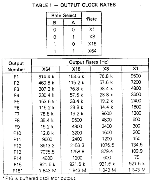
Using the X1 column of baud rates is perfect for the MC6802. The X16 column would nicely complete the most common baud rates.
The magical crystal to make these baud rates possible is 1.8432 MHz Fortunately, that crystal is readily available.
There were two iterations of this Serial I/O board. The first worked, but it only allowed one board to be in the system. (Also there were a few silkscreen issues) I wanted the ability to plug in two Serial I/O boards so here is version 1.1
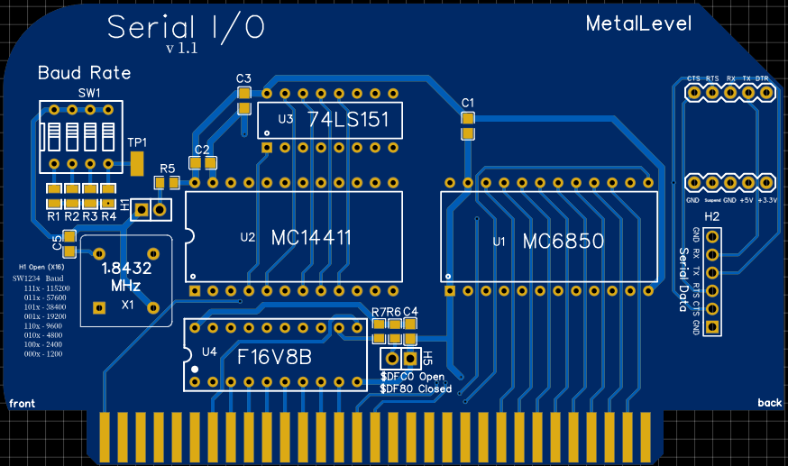
There are dip switches to select the X1 column baud rates. If H1 jumper is installed, then the X16 column baud rates are selected.
I added the H5 jumper to address the board in two different locations.
Finally, simple TTL logic was removed and the first ever F16V8B pal chip was added for address decoding. I had never used or programmed a PAL in the past, but after seeing how many 74xx chips I eliminated it was well worth the effort.
The PAL looks at the output of the H5 jumper, the VMA signal, and address lines A13..A6 The MC6850 has three chip select pins, CS0..CS2 The output of the address decoding from the PAL is hooked to CS2 CS0 is hooked to A15 CS1 is hooked to A14
Looking back, I did not use all the inputs of the 16V8 PAL. Having A15,A14 also hooked to the PAL would have made more sense. Then a single select into the MC6850 would be completely controlled by the PAL.
A note about the E signal and address decoding. The E signal is not used by the PAL for address decoding as it was for the ROM and RAM board. The MC6850 has an E input pin, as do most all MC68xx family ICs. Internally, the MC6850 guarantees the timing and synchronization with the E clock.
There are two break outs for the serial control lines.
The top one is for plugging in a usb to ttl serial module.
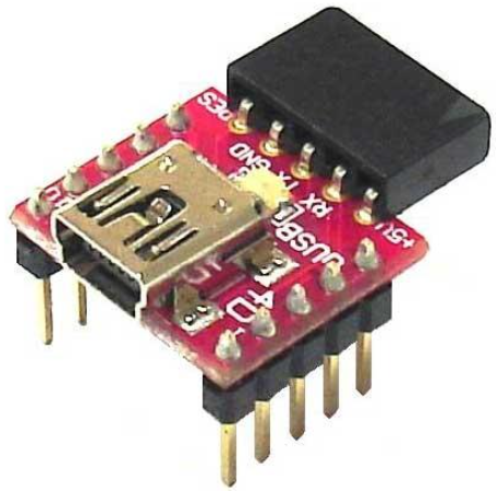
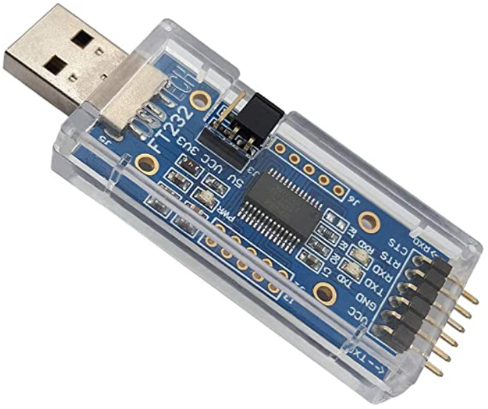
This module used the CP2102 chip, which I found very unreliable. I since moved to an external usb to serial module using the FTDI chip. Header H2 are the serial header pins that connect to this FTDI device.
The next revision of this board I will use the MCP2221 IC from MicroChip There will be a usb connection on the pcb. The MCP221 allows for customization of the chip for easy identification on the pc side. It also has serialization so cards can be numbered if desired.
Serial I/O is functional, and two cards can be plugged into the bus. Using a 2nd serial port to hook to a midi keyboard is now possible.
-->Next up, a hardware timer chip.
--> Previous
--> Home