Unlike the fully static W65C02S that Ben Eater used, the MC6802 must always have a minimum clock running to preserve the internal register states. This meant that the HALT line had to be used to control single stepping. I followed John Tsiombikas' YouTube video on how to single step a MC68000, which conveniently works with the MC6802.
Here is the original circuit from John's video:
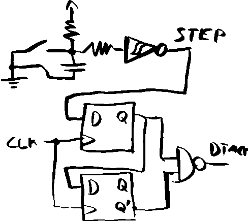
I breadboarded this circuit and tried it with my MC6802 computer. It worked. I had the Arduino Mega monitoring the address and data bus to see which instructions where being executed.
However, this differed once again from Ben's fully static 6502 variant in that I only got to see the address and opcode of the next instruction to execute. For example, On the 6502
lda #$ff
The arduino would show the address of the pc $8000, $a9 for the lda opcode on the bus followed by pc = $8001 and $ff on the data. Because Ben could single step the clock, you got to see the entire process of the instruction being executed.
However, on the MC6802, it is not fully static so I can't single step the clock, I have to single step using the HALT and E clock. So for the same load accumulator A with $ff
LDAA #$ff
I would see the pc address of $e000 and the opcode $86 for the LDAA. Now the next thing I see is not address $e001 and the $ff, but rather $e002 and whatever opcode is in the next instruction. Using the HALT on the MC6802 to single step, fully executes the instruction before returning to the HALT state. Not a big deal, but definitely not as nice and convenient as Ben's cpu.
It was time to convert this into a pcb. I've never made a pcb, nor I have I ever used a pcb design tool. After watching James Sharman build his pipelined cpu, I decided to give EasyEDA a try.
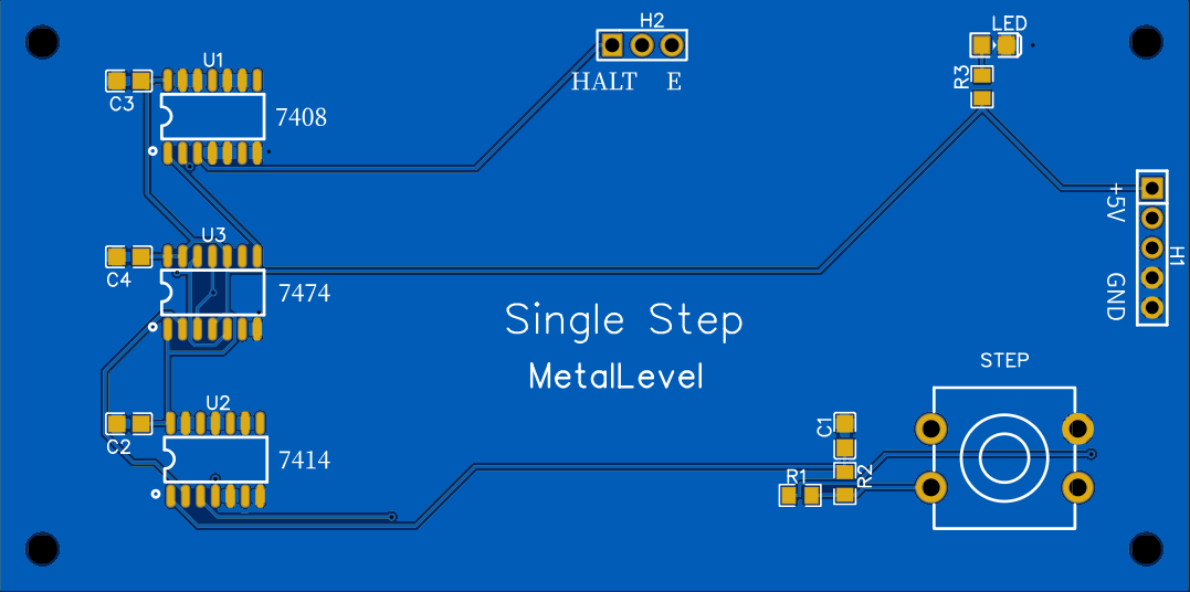
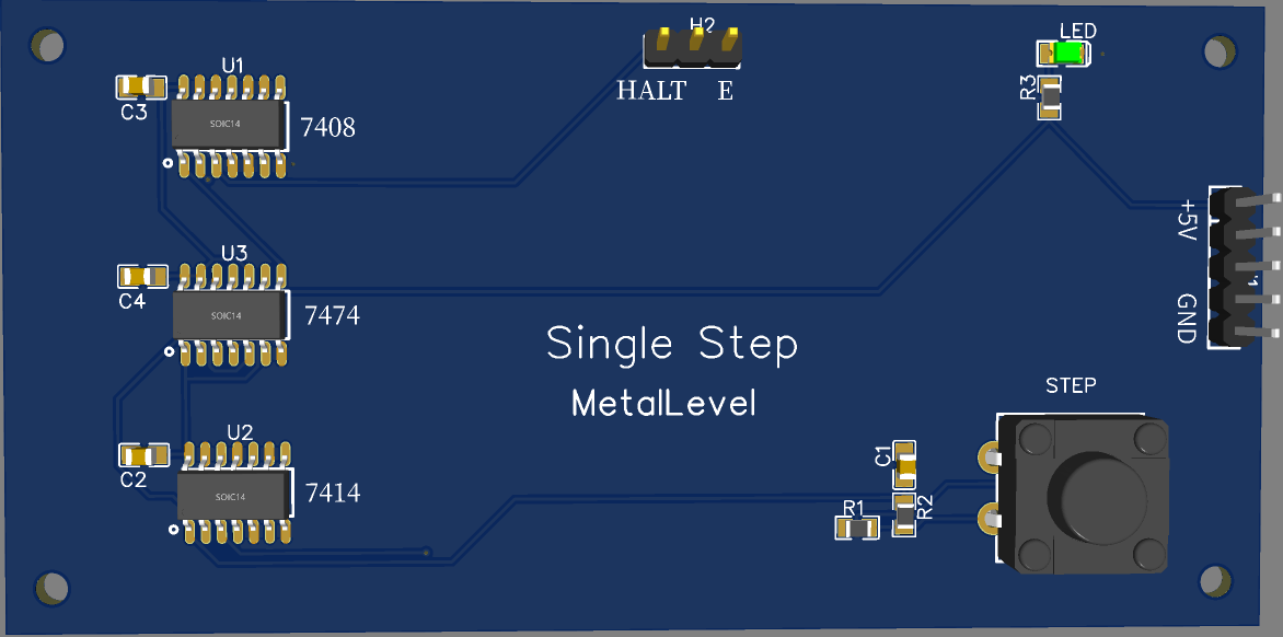
I ordered the boards from JLCPCB Costing roughly $5 for 5 boards, and $18 for DHL shipping, I received the first lot of pcbs. Not bad for under $5 a board.
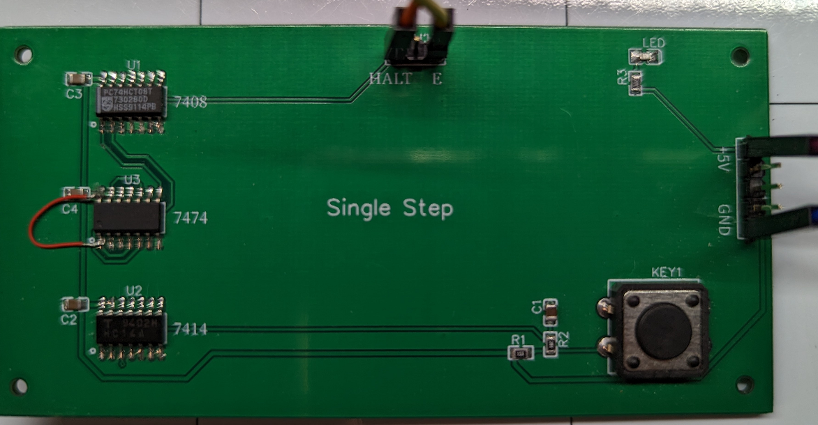
Ah! The dreaded bodge wire. I've seen them on boards before, but didn't know the proper terminology. I know now. I also learned what the pcb design software means by 'DRC check' I simply missed connecting two of the pins. It was a simple repair.
I powered the board using the jumpers on the right for +5V and GND. In the center are two jumpers, HALT and E These are tied to the equivalent pins on the CPU.
In order to do a single step execution, the HALT line must be brought high for one cycle and then returned low. The HALT line must go high before the rising edge of the E clock and back low after the trailing edge of the E clock. Even though the instruction may take 1, 2, 3 or more cycles to finish the instruction, the entire instruction is executed with as many cycles needed even though the HALT line has returned low. If the HALT line were to stay high for more E cycles than the instruction takes to execute, then more than one instruction would execute.
ok, time to make more pcbs.
Start with single chip boards.
--> ROM/RAM Modules
--> Previous
--> Home