The Single/Multi Step Controller is an external board (not and ISA board) that allows controlling the clock of the MC6802.
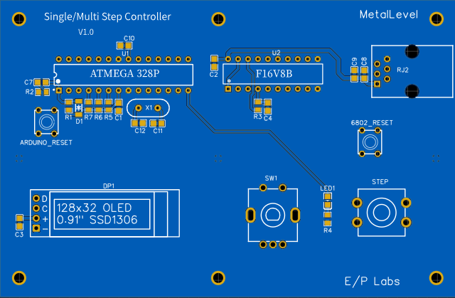
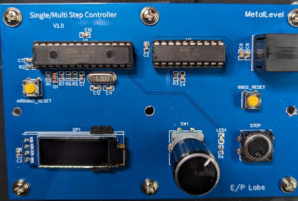 The 16V8 PAL performs the clock synchronization that is necessary. It also reduces the chip count.
(Remember the original single step board used three ICs, 7408, 7474, and 7414 to accomplish this)
The 16V8 PAL performs the clock synchronization that is necessary. It also reduces the chip count.
(Remember the original single step board used three ICs, 7408, 7474, and 7414 to accomplish this)
The RJ-11 plug is a 6 wire cable that connects to the cpu board to this board. The signals: RESET, E, and HALT from the cpu as well as 5v and GND.
The ATMEGA 328P controls the user input and the oled display. There are four modes of operation to choose from.
- Single Step
- Step 'N' times and stop
- Step 'N' times per second
- Free run
Single Step In this mode, each press of the STEP button advances the MC6802 one instruction.
Step 'N' times and stop In this mode, N is set using the rotary dial to any number between 0..1000 When the user presses the STEP button, N instructions are executed at the speed of the cpus 'E' clock.
Step 'N' times per second In this mode, the user sets the number of steps that will execute in one second. N can be between 1..40 N == 1 yields one instruction executing per second N == 10 yields 10 instructions executing per second with a 100ms delay between instructions N == 40 yields 40 instructions executing per second with a 25ms delay between instructions
Free Run In this mode, the cpu executes at the full speed of the E clock. This mode exists so you don't have to unplug this board to achieve full cpu speed.
The values configured by the user for each of these modes are stored in the arduino's eeprom so they survive power cycling.
There is a reset button for resetting the arduino, as well as a reset button for resetting the MC6802 cpu.
Each step that is performed will flash the LED next to the STEP button.
--> "You're going to need a bigger boat!"
--> Previous
--> Home