I chose the MC6802 because I acquired one back in 1980's. It was a chip I was intrigued with back then, and never having the opportunity to use it in my professional career, it remained on my bucket list of projects to 'get around to' sometime.
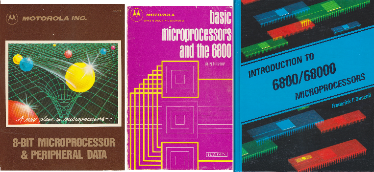
I bought these reference books new while still in college and they've been sitting on the shelf for decades until now.
I started on a breadboard, following Ben Eater's YouTube video of a 6502 and Arduino Mega. This is the first time I saw an Arduino used to monitor the address and data bus of a cpu. I followed his series of videos of the 6502, but used the MC6802 instead. This computer had rom, ram, PIA, serial port, and LCD screen very similar to Ben's 6502 breadboard computer.
The code in this rom would run a series of ram tests on the internal 128 bytes of the cpu, and then the 2k of static ram. The status and results of each test were displayed on the lcd screen and also sent over the serial port to the pc.
This is what I ended up with:
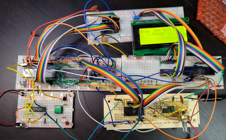
The CPU (MC6802)
The MC6802 is the same as the MC6800 with a few improvements...
- On-Chip Clock Circuit
- 128x8 Bit On-Chip RAM
- 32 Bytes of RAM are Retainable
- Software-Compatible with the MC6800 The internal ram is nice as it allows quicker prototyping by not having to wire up RAM. 128 bytes is enough for a stack and a few variables. The on-chip clock circuit also simplified the circuit when using a MC6802 over a MC6800.
The PIA (Peripheral Interface Adapter) is the MC6821
- It has two 8 bit I/O ports.
- PortA is the 8-bit data bus to the LCD
- PortB uses 3 control lines for the LCD
- It is bi-directional so the cpu can poll the lcd for busy/ready status.
The ACIA (Asynchronous Communications Interface Adaptor) is the MC6850
At this point I didn't have a baud rate generator chip, so I used a 555 timer with a POT and scope to get something close to an acceptable 2400 baud rate. Not pictured is a small USB to serial adapter hooked to the blue and purple wires (TX/RX pins) of the MC6850 I used Putty on the pc to communicate with the 6802.
The RAM is 2K static RAM (TMM2016-15)
This was used because I had several of these chips on hand.
The ROM is an 8K flash rom (AT28C64B)
I started with this for ease of programming. 8K of assembly instructions is a lot of code, so nothing larger was needed for now.
The LCD is a 4 line, 20 characters per line screen.
I purchased this on Amazon. It was marketed as an Arduino or RPI screen. It came with an I2C board which I removed so I would have access to the 8bit data bus and control lines directly.
Reset button
In the lower left of the picture, on the 1/2 whiteboard is a green reset button for resetting the cpu.
Single Step
Not shown is the single step circuit that I used to single step the 6802.
--> Previous
--> Home